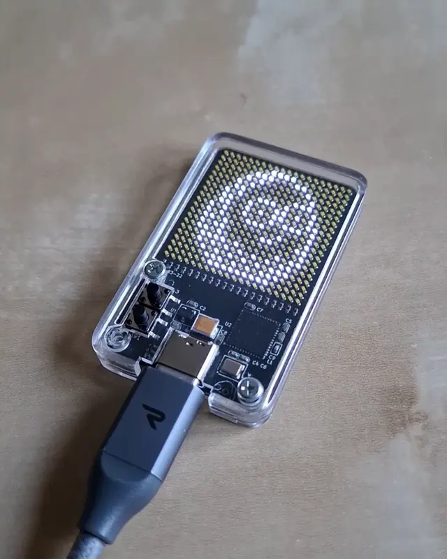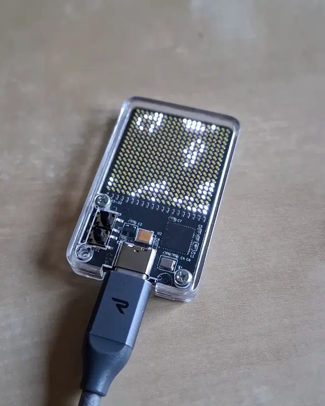
µLife - Conway's Game of Life Keychain
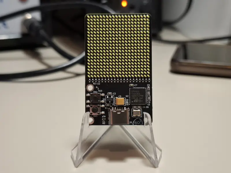
Compact keychain device running Conway's Game of Life on a 400-LED matrix using charlieplexing with STM32G431
Compact keychain device running Conway's Game of Life on a 400-LED matrix using charlieplexing with STM32G431
µLife (pronounced “mu-Life”) is a compact keychain device that runs Conway’s Game of Life on a 400-LED matrix, inspired by watching bitluni’s electronics videos and a recent C++ implementation of the cellular automaton for a school project.
Rather than build yet another LED matrix display, I decided to tackle the specific challenge of implementing a full Game of Life simulator in keychain form factor. This required solving several interconnected problems: controlling 400 LEDs with minimal GPIO pins using charlieplexing, achieving sufficient brightness in a power-constrained design, and creating professional firmware architecture with responsive user controls.
The project evolved through two prototypes. The initial proof-of-concept using a NUCLEO development board successfully demonstrated the charlieplexing concept but suffered from dim display and slow refresh rates. The final design with a custom STM32G431CBU6 board achieved 120 Hz flicker-free operation with significantly improved brightness by optimizing resistor values and leveraging a faster microcontroller.
The device successfully demonstrates Conway’s Game of Life with smooth animation, cryptographically random pattern generation using the STM32’s True-RNG module, and pre-programmed classic patterns including gliders and oscillators. Current consumption remains at 150mA, well below the 250mA design target.
Complete design decisions, assembly methodology, and troubleshooting process are documented in the development journal.
The core innovation lies in using charlieplexing to control a 20×20 LED matrix (400 LEDs) with only 21 GPIO pins from the STM32G431CBU6 microcontroller. This technique leverages tri-state logic to achieve N(N-1) addressable LEDs with N GPIO pins, compared to N²/4 LEDs with standard multiplexing.
The mathematical relationship for required pins is n = ⌈1 + √L⌉, where L is the number of LEDs. For 400 LEDs, this yields exactly 21 pins—a perfect match for the available GPIO count while leaving pins for power management and user interface. This efficient use of GPIO was essential to maintaining the compact keychain form factor.
The initial prototype suffered from insufficient brightness due to the brief duty cycle of charlieplexed LEDs (58 Hz refresh rate). Rather than accept this limitation, I systematically reduced the series resistors from 220Ω down to 1Ω, pushing the LEDs closer to their maximum current rating while maintaining GPIO safety margins within the 20mA source/sink capability.
This optimization increased brightness significantly, though the display still faces challenges in bright sunlight due to the fundamental physics of LED multiplexing. Indoor visibility is excellent, achieving the practical goal of a conversation-starting demonstration device.
The STM32F030R8 in the initial prototype proved inadequate for real-time Game of Life calculations at acceptable refresh rates. Upgrading to the STM32G431CBU6 provided 3.5× higher clock frequency (170 MHz vs 48 MHz) and 5× better computational performance (569 vs 106 CoreMark score).
This performance improvement enabled smooth 120 Hz flicker-free operation with responsive user controls, eliminating the visible flicker that plagued the first prototype. The upgrade demonstrated the importance of selecting appropriate hardware for real-time embedded applications.
Assembly costs were controlled by leveraging JLCPCB’s basic parts library, limiting non-standard components to five essential parts: MCU, TVS diode, LEDs, USB connector, and buttons. This strategy reduced setup fees from potentially €55+ to €14 across five boards.
The final cost achieved was €10.61 per assembled unit including professional PCBA service. This cost-effective approach made it feasible to produce multiple units for testing and refinement without breaking the budget on a learning project.
The firmware follows a layered architecture separating hardware abstraction, game logic, and user interface. Key features include detection of single, double, and long button presses, pre-programmed classic patterns (gliders, oscillators, spaceships), and cryptographically random grid generation.
The True-RNG implementation generates genuinely unique patterns—with 2⁴⁰⁰ possible grids, each random generation is statistically guaranteed to be unprecedented. The modular firmware design made it straightforward to add new patterns and user interactions during development.
The complete PDF documentation includes detailed technical diagrams, full circuit schematics, design decisions, testing procedures, and troubleshooting guides.
View Full Documentation